How to mount the control system
Use our video tutorials to mount a control system.
If you have installed SketchUp you can explore queen control system sketchup model with it.
Recommended additional purchase list
After you receive a queen pack, we recommend to purchase the following stuff:
item | photo | pcs | comments, requirements, models |
|---|---|---|---|
sheet of plywood or textolite |  | 1 | use a piece of plywood or textolite at least [630mm x 750mm] to mount the queen pack items |
electric box |  | 1 | you can optionally purchase electric box to hide the plywood or textolite, but not required |
tapping screws |  | many | depends on what kind of surface was chosen: plywood or textolite |
multimeter | 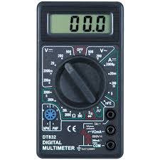 | 1 | use multimeter later to check the connections after the mount process |
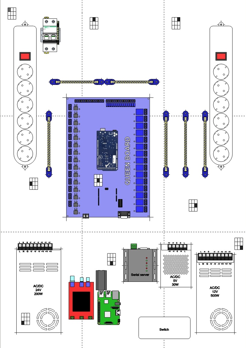
Queen Pack components locating
First place all the components on the plywood
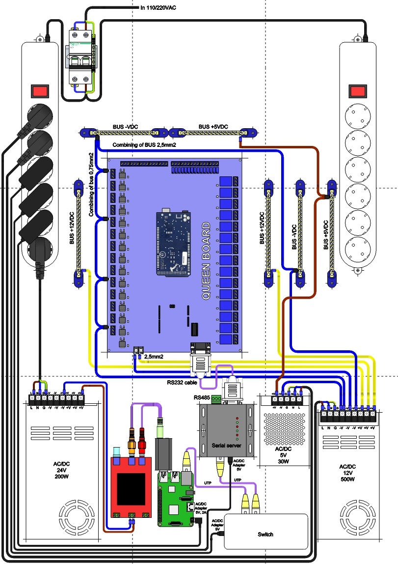
Wiring layout
Plug the components using wires and cables
Plugging various devices
Use the following connetions for plugging various devices:
Connection name | Photo | Description |
|---|---|---|
12VDC-RELAY-CONTROL |  | layout shows how to control 12VDC devices with a relay |
5VDC-RELAY-CONTROL | 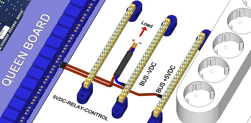 | layout shows how to control 5VDC devices with a relay |
VAC-RELAY-CONTROL | 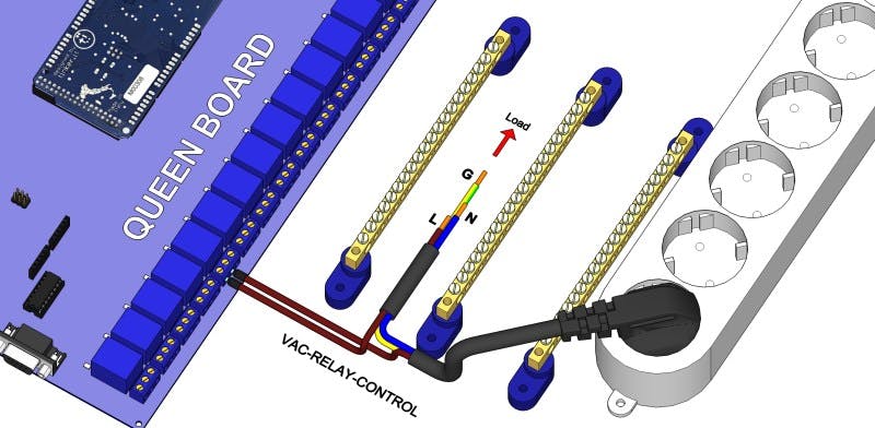 | layout shows how to control AC voltage devices with a relay |
CIRCUIT-RELAY-CONTROL | 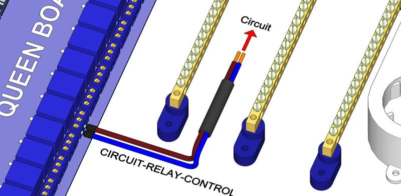 | layout shows how to short any contact (i.e. emulating the button press) with a relay |
12VDC-PWM-CONTROL | 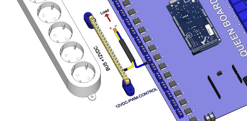 | layout shows how to smooth control 12VDC devices with a PWM transistor. Warning! maximum current is 2A per one channel (transistor), that is an equivalent 5m of the LED strip |
5VDC-PWM-CONTROL | 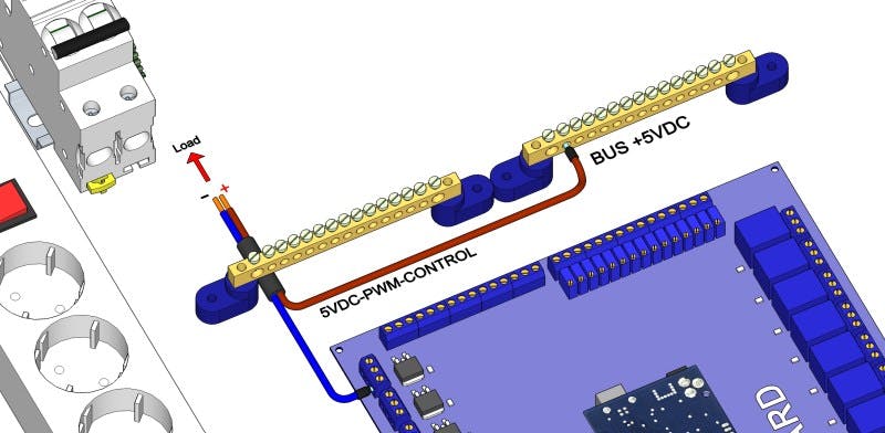 | layout shows how to smooth control 5VDC devices with a PWM transistor |
12VDC-POWER-SUPPLY | 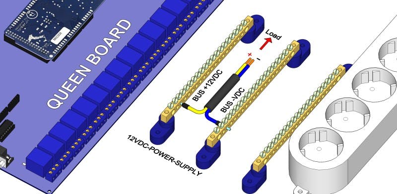 | layout shows how to make a static power for 12VDC devices |
5VDC-POWER-SUPPLY |  | layout shows how to make a static power for 5VDC devices |
VAC-POWER-SUPPLY | 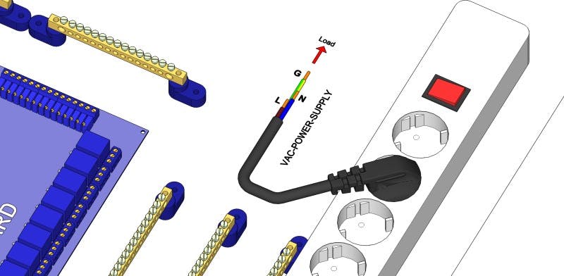 | layout shows how to make a static power for AC voltage devices |
DIN-PASSIVE | 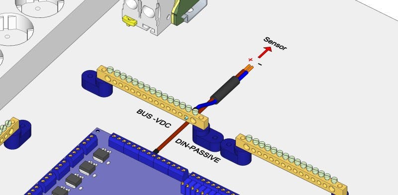 | layout shows how to plug dry contact sensors to the digital inputs |
AIN-PASSIVE | 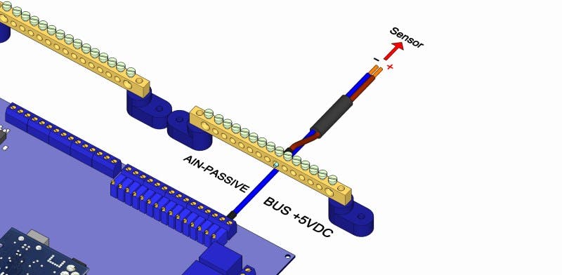 | layout shows how to plug dry contact sensors and resistive elements to the analog inputs |
DIN-ACTIVE | 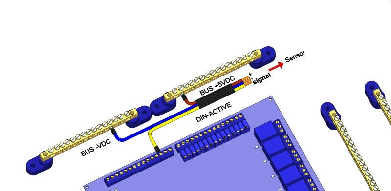 | layout shows how to plug active (powered) sensors to the digital inputs |
AIN-PASSIVE | | layout shows how to plug active (powered) sensors to the analog inputs |
Check the connections
Use multimeter to check the connections before you power on the control system. Also it is recommended to check 24V, 12V and 5V voltages after the power on, to be sure power supply is operable.